Thursday, 18 May 2017

R Class Loco Assembly Tips

Parts List


In addition to the 3D printed parts, the following parts must be obtained separately by the modeller:
  • For pre 2017 Models only - 2 brass I-beams (Special Shapes Part No. B-6-3)
  • Brass wire for handrails, etc. (0.4 mm, 0.6 mm)
  • Brass chain (40 links per inch) if modelling original version with chain "handrails" e.g. North Yard CH40 (2 packs required per loco)
  • Air hoses - e.g. Detail Associates #6206 (Vacuum brake hoses are included.)
  • Handrail Posts (4) for uncoupling levers - e.g. Markits 1.5 mm(short - available from Railwest Models.
  • Bogie drive mechanisms - see below (Hollywood Foundry)
  • Motor - Mashima 1833D Flat Can (double shaft, 2 mm diameter, includes fixing screws) (Hollywood Foundry)
  • Drive shaft(s) - 1.5 mm diameter, 65 mm long (cut to exact length) (Hollywood Foundry)
  • Universal Joint set for 1.5 mm shafts (Hollywood Foundry)
  • Flexible coupling(s) for motor end(s) of drive shafts - suggestion is to use model aircraft fuel tubing, approx. 1 mm ID, 4 mm OD.  
  • DCC decoder and speaker (both optional)
  • Light Emitting Diodes (LEDs) for headlights 4 x 3 mm (sunny white)
  • LEDs (red and white) and optic fibre, if operating marker lights desired
  • paint as desired
  • lead or other weighting material
  • Kadee couplers #156 ("scale") or #146 (normal size)
  • Kadee draft gear boxes #252
  • Fixing screws for body, couplers and fuel tank e.g. Kadee #256 - 12 holes are included correct size (1.8 mm) ready for tapping 2-56.
  • Fixing screws for speaker M1.4 x 6 (slightly longer is OK) - 4 holes are included correct size (1.1 mm) and screws should make their own thread, tapping shouldn't be required.  Suitable screws are available from DCC Concepts - Part No. DCS-PHB156 or in assortment DCS-PHBSet.  Although described as 1.5 mm, the DCC Concepts screws are actually M1.4 thread. Note:  DCC Concepts now supplies pan-head and countersunk screws interchangeably, so you can't be sure of getting one or the other.

Bogie Drive Mechanisms


The bogie drive mechanisms can be ordered direct from Hollywood Foundry. The ordering specifications are as follows:

Drive bogie specifications: G16.5/B28.6+25/W14-110/15:1DUALBELT/NOBOL
Dummy bogie specifications: G16.5/B28.6+25/W14-110/NOBOL

To order the above bogie configurations, please use the special order page on the Hollywood Foundry web site and copy and paste the above codes into the Product Description field.  

The modeller has the choice of fitting two identical drive bogies or one drive bogie and a matching dummy bogie, depending on the required hauling capacity.  

If a single drive bogie is fitted, this would normally be placed at the rear to keep the cab free for interior detailing if desired.  However, the drive shaft is quite low above the footplate level, so there is minimal intrusion into the cab when two drive bogies are fitted.

The current (February 2016) pricing for the required Hollywood Foundry parts is:

Drive bogie - $91.30 (same price as Bullant In-Line 3-Axle)

Dummy bogie - $52.80 (same price as Bullant 3-axle Dummy)
    Motor: Mashima M1833D - $31.35

    Universal Joint Set for 1.5 mm shafts (set contains parts for 4 joints.  1 joint is required per drive bogie, but it is recommended to purchase 1 set per loco to allow for some "spares".) - $4.19 per set

    Drive shafts are available from Hollywood Foundry although the required 65 mm length is not a standard product. Check with Hollywood Foundry for availability.  Alternatively, 1.5 mm brass or steel rod can be used.

    Silicone Tubing - used for flexible coupling between motor and drive shaft(s).  Supplied free by Hollywood Foundry if requested when ordering other parts.  Tubing will fit both 2 mm motor shaft and 1.5 mm drive shaft. 

    The prototype 3D-printed chassis showing central motor, Tsunami AT-style DCC sound decoder, drive shaft, belt drive and speaker "duct" with tunnel for drive shaft.
    The chassis does not have provision for a flywheel.  The main reason is that the motor is mounted low down, partly in the fuel tank, to get a "straight line" drive shaft alignment.  Also, the speaker is very close to one end of the motor, which was necessary to avoid the narrow part of the body just behind the cab.


    DCC and Sound


    The chassis is specially designed to accept a 23 mm square high-bass speaker (Soundtraxx 810129 or equivalent) if a sound decoder is to be installed.  The speaker faces downwards on a "sound duct" which has a "tunnel" through it for the front drive shaft.

    Although the choice of specific sound decoder is very subjective, the Soundtraxx Alco 244 Tsunami decoder sounds similar to the English Electric diesel engine in the prototype, and is probably the closest available "off-the-shelf" decoder.  The Tsunami "AT" style decoder model 828043 (pictured above) is suitable and slightly cheaper than the TSU-1000 style model 827104.

    Note: The above links are for the SoundTraxx web site.  SoundTraxx do not sell direct but their products are available from many retailers.


    Couplers


    The suggested couplers are both "long shank" style which avoids the problem of the "glad hand" on opposing couplers from fouling the cowcatcher.  The choice between normal and "scale" size is up to the individual modeller.

    Also, the suggested Kadee #252 draft gear boxes should be mounted upside down (as per the photo on the right on the Kadee web site). The round boss on the upper side needs to be trimmed away to allow the assembled coupler to slide into the headstock opening.

    Other types of couplers can potentially be installed by modifying the headstock and/or coupler mounting pad.


    Handrails and Chains


    As delivered, the R class had round handrail posts with chain between them rather than solid handrails.  This was a feature of the R class and was necessary to allow the doors on the side of the long hood to be opened.

    Later, the chains were replaced with solid handrails but with removable segments to allow the doors to be opened.

    The 3D-printed chassis incorporates slots intended to house 2 mm x 0.25 mm brass strip soldered to the bottom of each handrail post, of which there are 25.  This approximates the prototype bracket arrangement and allows the handrail posts to be positioned right at the edge of the footplate.

    The handrail posts can be made from 0.6 mm brass wire and should be 16.7 mm high.  The brass strip should be soldered to the bottom of each post, with 1.1 mm overlap, and project a maximum of 1.8 mm below the bottom of the handrail post.  A suggested construction method is to leave the brass wire and strip as long lengths, and tape them down to a heat resistant surface with the  required overlap, then solder the joint and trim both to the required length.  The brass strip will probably require filing to remove any rough edges prior to insertion into the slots in the chassis.

    Suitable chain is available from North Yard in New Zealand, part number CH40 (300 mm length).  Two packs are required per loco.  Railwest Models normally stock this chain also.

    Chassis - Removal of Support Material

    Carefully cut away the support materials from the delicate areas highlighted in the drawing below which are:
    • Bolsters with bogie chain brackets approx. 6 mm in from edge of footplate (2 per side)
    • Triangular footplate supports (4 per side)
    • Sandboxes (2 per side)


    Once these areas have been done, the remainder of the support material can be gently torn away by wiggling a section of it to break the fine attachment points.  

    The remnants of the support attachment points should be removed with a sharp hobby knife, filing or sanding on all visible areas, including the bogie attachment points.

    Chassis - Assembly of Brass I-Beams (Pre 2017 Models Only)


    From 2017, the I-Beams are included in the 3D-printed chassis.  The brass I-Beams are not required.

    The underside of the chassis includes two longitudinal slots which are designed to provide a secure attachment for the brass I-beams.  The brass I-beams add some weight and rigidity to the chassis, as well as replicating the appearance of the steel I-beams in the prototype chassis.

    Cut the brass I-beams to a length of 236 mm, or a fraction under.  The I-beams should fit between the inside of the headstocks with a small amount of room at each end so that they do not exert any outward pressure on the headstocks.  Keep the offcuts as they will be useful for checking the fit of the I-beams in the mounting slots.

    At this stage, it is advisable to cut 3 notches in the lower inside flange of each I-beam to facilitate later access to the fixing screws which attach the chassis to the body.  The suggested shape of the notches is highlighted in yellow below.


    The diagram below is a cross-section of the footplate, with the I-beams highlighted in yellow.  The intention is that the I-beams are inserted into the slots, then slid outwards so that the flange on the I-beam engages in the groove to provide a secure attachment.


    Once the support materials have been removed from the underside of the chassis, it will be necessary to do some cleaning up of the I-beam slots.  Firstly, check for any remnants of supports materials on the inside surfaces of the slots and, in particular, in the narrow groove. Cut away any remnants with a sharp hobby knife.

    After filing any burs from the cut end of an offcut of I-beam, test fit it to see whether it will slide into the groove at various locations along the length of the chassis.  Moderate pressure with a screwdriver will probably be required to encourage the I-beam to slide sideways into the groove.  If there are tight spots, don't force it at this stage, as the groove will probably require cleaning out.

    It may be necessary to make a tool from metal strip approx. 6 x 0.5 mm, by bending the first 3 mm from the  end of the strip at right angles.  Insert the bent end of the tool into the groove and slide it along to find and remove any remnants of plastic support material which may be obstructing the groove.  Be careful not to damage the triangular supports under the footplate, the bolster ends or sandboxes.

    Once the groove has been cleaned out so that the offcut of I-beam fits at any point along it, insert the full-length I-beam and gently slide it sideways to engage in the groove.  When satisfied that the I-beam is fully engaged in the groove along its full length and the notches in the lower flange are aligned with the fixing screw locations, it can be glued in position.

    Chassis Height


    The finished height of the footplate should be 23 mm.  Spacers with a nominal thickness of 1 mm are required between the Hollywood Foundry bogies and the underside of the footplate.  The thickness of the spacers can be varied slightly, if required, to adjust the coupler height to match a Kadee coupler height gauge.

    Sunday, 11 September 2016

    AQNY AZKY Assembly Tips

    Parts List (for HO scale model)

    • Bogies: e.g. Kato 31-602 Barber S-2 Roller Bearing Bogies with 840 mm (33") wheels. 
    • Couplers: Kadee #148 or #158
    • Coupler boxes: Kadee #252 (supplied)
    • Air Brake Hoses, e.g. Detail Associates #6206 or Kadee #438.
    • Brake wheel e.g. Kadee #2025 or similar
    • Brass wire: 0.3 mm and 0.4 mm for handrails, and brake piping
    • Fixing screws: (see below)
    • Glue, paint, decals
    • The AQZY (ammonia tank wagon) requires a tank from a Frateschi chemical tank car.  These cars are available from some Perth hobby shops or online.  The Frateschi tank is slightly smaller than scale size but is a pretty good representation of the prototype tank.
    Marbelup Models has limited stocks of the Kato bogies for sale.

    Removing Support Structures


    Carefully remove the support structure from the wagon.  It is suggested to use a sharp knife to cut the supports away from visible areas and delicate parts.  Take particular care around the bottom of the steps, and the triangular bracing inside the centre portion of the wagon.

    The following image highlights the more delicate parts, some of which are only visible once the outer layers of supports have been cut away.


    Once the majority of the support structure has been removed, carefully go over the wagon and cut away the small supports which typically extend from one part to another including, for example, on the end ribs and bogies bolsters.  An Exacto type hobby knife with a sharp pointed blade (Exacto #11 or similar) is quite useful for getting into the nooks and crannies.

    Go over the model and smooth off any remnants of the fine supports, expecially in the visible areas.  A sanding stick or small file can be useful for this.

    Bogie and Coupler Mounting Holes


    The mounting holes for the couplers and bogies have been printed at 1.8 mm diameter to suit 2-56 screws.  

    Due to the difficulty of tapping the blind holes for the bogies, the 3D print includes vertical grooves in the sides of the holes to help the screws cut their own threads, so tapping the holes is not required nor recommended.  Note that the depth of the blind holes is 3.3 mm.  The bogie fixing screws may need trimming to avoid damaging the floor of the wagon.

    The wagon includes projections from the bolsters, to match the height of the Kato bogies, and provide "3-point suspension" to minimise side-to-side rocking of the wagon.  If fitting other types of bogies, these projections may need to be modified or removed.

    The holes for mounting the couplers are also blind, but should be drilled right through the floor with a 1.8 mm drill to obtain a strong fixing.  These holes should be tapped 2-56.  Note that one end of the wagon has two blind holes for couplers.  The one closest to the end of the wagon is for a Kadee coupler and the hole closest to the bogie fixing holes is for the rotary coupler option.

    Note: An economical source of steel 2-56 screws in various lengths is Little Bird Electronics.  

    Bogies


    The suggested bogies are Kato 31-602.  These are pretty much "exact", differing only in having 2 springs visible at the bolster ends rather than 3. Note that the Kato bogies have the correct size wheels 840 mm (33") which are smaller than those fitted to most other Westrail standard gauge wagons.

    Note that the depth of the blind holes for the bogies is 4.3 mm.  The fixing screws may need trimming to avoid damaging the floor of the wagon.  Do not drill the bogie mounting holes right through, as they will be visible on the finished model.

    Note that the height from rail level to the top of coupler mounting surface should be 11.5 mm, the standard for Kadee couplers.

    Couplers


    Because of the thin floor section, the model has been designed so the coupler and draft gear box slide into a recess in the end sill.  Make sure that any remnants of support structure from the 3D printing process have been cleaned up from inside the coupler mounting recess.

    You will need to remove the cylindrical projection from the top of the Kadee #252 draft gear boxes - highlighted in red in the diagram below.


    The draft gear box will probably be a snug fit inside the mounting recess.  A hole has been provided for a 2-56 fixing screw to prevent the coupler from being pulled out.  Note that the maximum length of the screw is 3.9 mm, so it is likely the screw will have to be cut to length.  Provided a metal screw is first used to create a thread in the provided hole, a nylon screw (e.g. Kadee #256) can be used for the permanent fixing.  A nylon screw is much easier to cut to the desired length.

    Kadee nylon 2-56 screws are available from good hobby shops.

    Brake Piping


    The brake piping can be formed from 0.3 and 0.4 mm brass wire.  There are long, angled pipes at each end, and short 90 degree pipes connecting to the brake valve/cylinder assembly.  The main pipes running along the inside of the wagon frame are printed in place.

    The diagram below shows the approximate dimensions for forming the brake piping.

    The shorter pipe to the brake cylinder is 0.4 mm as is the long pipe at the same end.  The other 2 pipes should be 0.3 mm.

    Small starter holes have been provided for attachment of the brake piping.  These should be opened out with a small drill bit or broach.  (Sets of tapered broaches are available from good hobby shops.)


    Handrails 


    The wagon has short handrails at each corner, and an L-shaped handrail attached to the brake wheel supports.  These can be formed from 0.4 mm brass wire.  Small starter holes have been provided to locate the handrails, which should be drilled out, e.g. with a 0.45 mm drill bit in a pin vice.

    The holes for the horizontal four handrails are 4.3 mm apart (centre to centre).  These handrails should be bent with an inside radius of approx. 0.6 mm (e.g. using a 1.2 mm drill bit).  The total height of the handrails should be approx 2.5 mm and, when installed, the top of the handrail should be 1 mm above the wagon deck.

    The L-shaped handrail should also be bent with a inside radius of approx. 0.6 mm.  The horizontal leg should be approx. 6.5 mm long, and the vertical leg approx. 7.5 mm long.

    All handrails should be fixed into position with superglue.


    Air Brake Hoses


    Small brackets are provided next to the couplers on each end of the wagon for air brake hoses.  Cast plastic hoses are available from Detail Associates, part number 6206.  Carefully drill out the starter hole provided in the supporting bracket to suit the diameter of the "pipe" on the air hose.  A suggested drill size is 0.65 mm.

    An alternate (cheaper) brake hose is the Kadee #438.  These have a rectangular mounting pin which requires the holes to be drilled out to approx. 0.8 mm.  It is suggested to drill the holes out in a number of stages, using successively larger drill bits, to avoid over-stressing the brackets.

    Uncoupling Levers


    Notched brackets have been provided at both ends of the wagon for the uncoupling levers, together with a longitudinal hole just below the coupler.  The uncoupling lever can be shaped from 0.4 mm brass wire.   The diagram below shows the approximate shape to aim for, but feel free to adjust the measurements to suit your model.


    After positioning the uncoupling lever, check that the coupler can swing freely and is not obstructed, prior to gluing it into position.

    Handbrake Wheel


    A 0.5 mm spigot has been provided on the handbrake assembly, to which the wheel can be glued.  If necessary, open out the central hole in the handbrake wheel with a 0.6 or 0.7 mm drill bit to fit over the spigot.

    Weighting


    With the suggested Kato bogies, the completed AQNY weighs approx. 24 grams.  For this length wagon, the NMRA recommended weight is 125 grams, although some modellers feel that the NMRA weight recommendations are excessive.  A total weight of somewhere between 100 and 115 grams is probably about right.

    Due to the "skeletal" design of the wagon, there is not much scope to add weight where it can't be easily seen.  Weight can potentially be added to the container "load".  If using the Marbelup Models BIS sulphur containers, provision has been made to fix weights inside the containers.  It is suggested that any added weight be concentrated over the bogie ends of the containers, to avoid causing the wagon to sag in the long term.

    Painting


    Either enamel or acrylic hobby paints can be used to paint the finished model.  The model pictured has been painted with Testors Model Master Enamel colour "Gelb RLM 04".  (Gelb is German for yellow!)  A white undercoat (e.g. Testors Model Master 2748 enamel) is recommended to enhance the yellow colour.  

    Wednesday, 31 August 2016

    Marbelup Models Home Page

    High quality 3D-printed models of Western Australian trains in Sn3½ Scale (mostly) and HO Scale.

    New: Westrail DB Loco Project.


    For information about pricing and availability of any of these models, please send email to marbelupmodels@iinet.net.au

    Tuesday, 21 June 2016

    WO Assembly Tips

    Parts List

    • Bogies: e.g. "100-ton roller bearing" by Kadee part no 569 or 1569 (see below) or Tichy #3009 (1 pair) or #3036 (10 pairs)
    • Couplers: Kadee #148 or #158 or Glatzl rotary & dummy couplers (see below)
    • Replacement Metal Wheelsets 36" diameter - if using Tichy bogies, e.g. Intermountain #40051 (4 per wagon).
    • Coupler boxes: Kadee #262 (supplied)
    • Air Brake Hoses, e.g. Detail Associates #6206
    • Brass wire: 0.4 mm for handrails, etc. (approx. 1.5 x 300 mm lengths required per wagon)
    • Fixing screws: (see below)
    • Glue, paint, decals
    Marbelup Models can a supply "Parts Kit" containing all of the above items, with the exception of glue, paint and decals, with a choice of Kadee or Tichy bogies.

    Removing Support Structures


    Carefully remove the support structure from the wagon.  It is suggested to use a sharp knife to cut the supports away from visible areas and delicate parts.  Take particular care around the bottom of the ladders, and the various items of brake gear on the bottom of the wagon.

    The following images highlight the more delicate parts, some of which are only visible once the outer layers of supports have been cut away.


    Once the majority of the support structure has been removed, carefully go over the wagon and cut away the small supports which typically extend from one part to another including, for example, on the end ribs and bogies bolsters.  An Exacto type hobby knife with a sharp pointed blade (Exacto #11 or similar) is quite useful for getting into the nooks and crannies.  

    Go over the model and smooth off any remnants of the fine supports, expecially in the visible areas.  A sanding stick or small file can be useful for this.

    Bogie and Coupler Mounting Holes


    The mounting holes for the couplers and bogies have been printed at 1.8 mm diameter to suit 2-56 screws.  

    Due to the difficulty of tapping the blind holes for the bogies, the 3D print includes vertical grooves in the sides of the holes to help the screws cut their own threads, so tapping the holes is not required nor recommended.  Note that the depth of the blind holes is 4.4 mm.  If using Kadee bogies, the supplied screws may need trimming to avoid damaging the floor of the wagon.

    The holes for mounting the couplers are also blind, but should be drilled right through the floor with a 1.8 mm drill to obtain a strong fixing.  These holes should be tapped 2-56.  Note that one end of the wagon has two blind holes for couplers.  The one closest to the end of the wagon is for a Kadee coupler and the hole closest to the bogie fixing holes is for the rotary coupler option.

    Note: An economical source of steel 2-56 screws in various lengths is Little Bird Electronics.  

    Bogies


    The suggested bogies are Kadee #569 or #1569, the only difference being the width of the wheels.  Atlas and Athearn and others make similar bogies, but the advantage of the Kadee ones is that they add some weight to the wagon due to the use of a relatively heavy plastic material.

    Tichy Train Group also makes an economical 1-piece plastic bogie #3009 (1 pair) or #3036 (10 pairs), however these are supplied with relatively low quality plastic wheelsets which are also too small in diameter (33").  Intermountain Railway Company sell high quality all-brass wheelsets which fit well in the Tichy bogies and are the correct size, i.e. 36".

    Note that Intermountain do also sell complete roller bearing bogies but these are supplied with 33" wheelsets only.  Be wary of other brands of bogies as well.  In general, US roller bearing bogie (trucks) described as "100-ton" have 36" wheelsets and "70-ton" have 33" wheelsets.

    Note that the depth of the blind holes for the bogies is 4.4 mm.  If using Kadee bogies, the supplied screws will need trimming to a length of 7.5 - 8 mm to avoid damaging the wagon (or shorter screws substituted).  Do not drill the bogie mounting holes right through, as they will be visible on the finished model.

    Note that the height from rail level to the top of coupler mounting surface should be 11.5 mm, the standard for Kadee couplers.

    Couplers


    Option 1 - Kadees


    The WOB is designed for Kadee "whisker" couplers.  Either the #158 (scale size) or #148 (normal size) couplers can be used, with #262 draft gear boxes.

    The draft gear boxes supplied with the couplers do not fit as they have a different mounting hole position.  The #262 draft gear boxes (supplied) are narrower and have been used because they allow details such as the brake hoses to be positioned the scale distance from the wagon centre line.  Also, the #262 draft gear boxes are easier to use as the lid snaps into position.

    Ideally, the coupler fixing screws should be trimmed to exact length so that the end of the screw is flush with the inside of the floor.  Nylon screws (e.g. Kadee #256) can be used, as they are much easier to cut to the desired length.

    Kadee nylon 2-56 screws are available from good hobby shops.

    Option 2 - Glatzl (Sergent) Rotary Couplers


    If desired, the wagons can be fitted with a rotary coupler at one end, as per the prototype, to facilitate unloading in a rotary car dumper (tippler).  Glatzl sell working rotary couplers and matching dummy couplers which are available from Sergent Engineering in the US.  The Glatzl couplers will couple with "scale" size Kadees but not with "standard" size Kadees.

    Note that it is preferable to use Glatzl dummy couplers rather than a "scale" size Kadee for the "fixed" coupler as the relatively tight fight between the Glatzl rotary and dummy couplers results in better operation with a rotary car dumper.  On the Sergent web site, the dummy couplers are listed under the "economy" tab.

    Typical steps to fit a Glatzl rotary coupler are:

    1. Cut the rear portion off the Glatzl draft gear box leaving 16 mm of the draft gear box remaining.
    2. Drill a 2.3 mm diameter hole exactly in the centre of the circular mould mark in the coupler box.
    3. Fix the coupler to the end of the wagon opposite the ladder and handbrake wheel using a 2-56 screw.
    To fit a Glatzl dummy coupler:
    1. Use a round needle file to slightly enlarge the hole in the shank of the dummy coupler so that it pivots easily in a Kadee #262 draft gear box.
    2. Cut away a small amount of plastic from the rear of the coupler knuckle to allow the coupler to fully swing from side to side in the Kadee #262 draft gear box.
    3. Assemble the couple in the #262 draft gear box and snap on the lid.  Fix the assembled coupler to the end of the wagon with the ladder and handbrake wheel using a 2-56 screw.
    Ideally, the coupler fixing screws should be trimmed to exact length so that the end of the screw is flush with the inside of the floor.  Nylon screws (e.g. Kadee #256) can be used, as they are much easier to cut to the desired length.

    Kadee nylon 2-56 screws are available from good hobby shops.

    The height of the installed Glatzl coupler (rotary and dummy) should match the Kadee coupler height gauge.

    Brake Rods


    There are 4 brakes rods which can be formed from 0.4 mm brass wire.  The following diagram indicates the locations.

    Typically, the holes for the brake rods are printed at 0.4 mm diameter but all will require cleaning out using a pin vice and drill bit, e.g. 0.45 mm.

    The two shorter brake rods should be approx. 15.7 mm and 16.2 mm long, with 90-degree bends at both ends.  The bent ends fit into the hole in the brake levers.

    The two longer brake rods should be approx. 19.5 mm and 21.5 mm long, with a 90-degree bend at one end, approx. 1 mm long.  The straight end fits in the hole provided near the bogie pivot hole and the bent end fits into the corresponding brake lever.

    Handrails and Safety Rails 


    The WO has short handrails at each corner, mounted on the side of the rectangular "buffers".  Small starter holes have been provided to locate the handrails, which should be drilled out, e.g. with a 0.45 mm drill bit in a pin vice.

    The handrails can be formed from 0.4 mm brass wire.  They are actually semicircular, and are 1.5 mm wide (centre to centre) and 1.75 mm high, which allows for 1 mm to be inserted into the holes.

    This great photo from Rail Heritage WA of a WO under construction at
    Midland Workshops clearly shows the semicircular handrails.
    There are also "safety rails" running along the bottom of each side of the wagon, between the ladders.


    The safety rails are approx. 95 mm long - check this measurement on the actual wagon before cutting the wire.  They require a slight bend 10 mm from each end, so that the ends fit behind the vertical members of the ladders.  Small grooves have been provided on the rear of the ladders to locate the ends of the rails.  Along the sides of the wagons, the rails fit into the base of the side ribs, on top of the protruding flange.


    Air Brake Hoses


    Small brackets are provided next to the couplers on each end of the wagon for air brake hoses.  Cast plastic hoses are available from Detail Associates, part number 6206.  Carefully drill out the starter hole provided in the supporting bracket to suit the diameter of the "pipe" on the air hose.  A suggested drill size is 0.65 mm.

    Uncoupling Levers


    Notched brackets have been provided at the handbrake end of the wagon for the uncoupling lever, which runs across the full width of the wagon.  Note that there is no uncoupling lever at the other end of the wagon, as this is the rotary coupler end on the prototype.  The uncoupling lever can be shaped from 0.4 mm brass wire.   The diagram below shows the approximate shape to aim for, but feel free to adjust the measurements to suit your model.

    Diagram to be added.

    After positioning the uncoupling lever, check that the coupler can swing freely and is not obstructed, prior to gluing it into position.

    Handbrake Wheel


    A 0.5 mm spigot has been provided on the handbrake assembly, to which the wheel can be glued.  If necessary, open out the central hole in the handbrake wheel with a 0.6 or 0.7 mm drill bit to fit over the spigot.

    Weighting

    Details to be added.

    With the suggested Kadee bogies, the completed WO weighs approx. ?? grams.  For this length wagon, the NMRA recommended weight is ?? grams, although some modellers feel that the NMRA weight recommendations are excessive.  A total weight of somewhere between ?? and ?? grams is probably about right.

    Painting


    Either enamel or acrylic hobby paints can be used to paint the finished model.  The model pictured has been painted with Testors Model Master Enamel colour "Gelb RLM 04".  (Gelb is German for yellow!)  A white undercoat (e.g. Testors Model Master 2748 enamel) is recommended to enhance the yellow colour.  

    Friday, 1 January 2016

    WAGR Clerestory Roof Z Van

    WAGR Clerestory Roof Z Van (also Commonwealth Railways NY and NYA)


    These guards vans date from the late 1890's and there were versions with platforms at one end or both ends.  Some lasted into the 1970's in departmental service so, even in the diesel era, it would not be out of place to have one parked on a siding or as part of a work train.  In the early years of the 20th century, these vans were the main type to be found on goods trains.


    Quite a few were transferred to Commonwealth Railways during WWII as class NY and NYA.  New Zealand railways had some very similar vans (single ended) which have been previously available as brass models in  Sn3½ scale.  Correct bogies are available for the Sn3½ version from North Yard in New Zealand.

    For more information on the prototypes, please see the WA Wagon Pages for Single Platform and Double Platform vans.  For information on the Commonwealth Railways vans see the Comrails web site.  There are also a few photos of the vans at Rail Heritage WA.  Tip: Search for "clerestory" with both the Title and Caption fields ticked.

    Screenshot of Single Platform Van (including dogbox)
    Marbelup Models currently has both single-platform and double-platform versions available to order in  Sn3½ scale, and also in 4 mm scale.  The vans can potentially be produced for HOn3½ (or even HOn3) and O scale if their is demand.

    The model consists of two 3D-printed parts, containing most details including running boards, brake stand(s), brake hoses and chimney.  The modeller must add some details, including handrails (on the ends and side), and truss rods.  The modeller must also obtain bogies and couplers.  Marbelup Models has ordered a small quantity of NorthYard bogies which will be available for sale.  For more information on the parts required and construction techniques, see the Assembly Tips.

    As with many rail vehicles, there were variations between different batches of vans and modifications carried out during their long lifetime.  The model depicts the vans generally as they were later in their life, but is not necessarily 100% accurate for any particular van.  The clerestory windows have been opened out on the model, but some vans has "solid" windows.

    Friday, 13 November 2015

    WW Assembly Tips

    Parts List

    • Bogies: e.g. "100-ton roller bearing" by Kadee part no 569 or 1569 (see below) or Tichy #3009 (1 pair) or #3036 (10 pairs)
    • Couplers: Kadee #148 or #158 (see below)
    • Replacement Metal Wheelsets 36" diameter - if using Tichy bogies, e.g. Intermountain #40051 (4 per wagon).
    • Coupler boxes: Kadee #262 (supplied)
    • Air Brake Hoses, e.g. Detail Associates #6206
    • Brass wire: 0.4 mm for handrails, etc.
    • Fixing screws: 2 x 2-56 x 8 mm (5/16") metal, 2 x 2-56 x 12 mm (1/2") nylon - (see below)
    • Glue, paint, decals

    Removing Support Structures


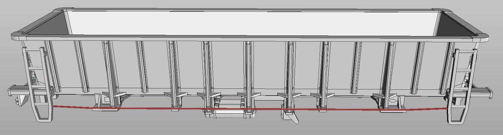
    Carefully remove the support structure from the wagon.  It is suggested to use a sharp knife to cut the supports away from visible areas.  Take particular care around the roofwalk supports at the ends of the wagon, and the discharge hatches at the bottom of the wagon.  There should be a row of supports along each side of the wagon, under the side sills.  Once these are removed, the supports under the discharge hatches will be visible.

    Typical Support Structure prior to removal.
    Once the majority of the support structure has been removed, carefully go over the wagon and cut away the small supports which typically extend from one part to another including, for example, inside the coupler housing.  An Exacto type hobby knife with a sharp pointed blade (Exacto #11 or similar) is quite useful for getting into the nooks and crannies.  

    Go over the model and smooth off any remnants of the fine supports, expecially in the visible areas.  A sanding stick or small file can be useful for this.

    Bogie and Coupler Mounting Holes


    The mounting holes for the couplers and bogies have been printed at 1.8 mm diameter to suit 2-56 screws.  

    Due to the difficulty of tapping the blind holes for the bogies, the 3D print includes vertical grooves in the sides of the holes to help the screws cut their own threads, so tapping the holes is not required nor recommended.

    Note: An economical source of steel 2-56 screws in various lengths is Little Bird Electronics.  

    Bogies


    The suggested bogies are Kadee #569 or #1569, the only difference being the width of the wheels.  Atlas and Athearn and others make similar bogies, but the advantage of the Kadee ones is that they add some weight to the wagon due to the use of a relatively heavy plastic material.

    Tichy Train Group also makes an economical 1-piece plastic bogie #3009 (1 pair) or #3036 (10 pairs), however these are supplied with relatively low quality plastic wheelsets which are also too small in diameter (33").  Intermountain Railway Company sell high quality all-brass wheelsets which fit well in the Tichy bogies and are the correct size, i.e. 36".

    Note that Intermountain do also sell complete roller bearing bogies but these are supplied with 33" wheelsets only.  Be wary of other brands of bogies as well.  In general, US roller bearing bogie (trucks) described as "100-ton" have 36" wheelsets and "70-ton" have 33" wheelsets.

    Note that the depth of the blind holes for the bogies is 4 mm.  If using Kadee bogies, the supplied screws will need trimming to a length of 7.5 - 8 mm to avoid damaging the wagon (or shorter screws substituted).  Do not drill the bogie mounting holes any deeper, as they are directly under the ends of the hopper and the drilled hole will "break through" and be visible on the finished model.

    Couplers


    The WW is designed for Kadee "whisker" couplers.  Either the #158 (scale size) or #148 (normal size) couplers can be used, with #262 draft gear boxes.

    The draft gear boxes supplied with the couplers do not fit as they have a different mounting hole position.  The #262 draft gear boxes, which are available separately, are narrower and have been used because they allow details such as the brake hoses to be positioned the scale distance from the wagon centre line.  Also, the #262 draft gear boxes are easier to use as the lid snaps into position.

    Because of the deep end sill on the WW series of wagons, the model has been designed so the coupler and draft gear box slides into a recess via a hole in the end sill.  Make sure that any remnants of support structure from the 3D printing process have been cleaned up from inside the coupler mounting recess.

    The draft gear box will probably be a snug fit inside the mounting recess.  A hole has been provided for a 2-56 fixing screw to prevent the coupler from being pulled out.  Note that the maximum length of the screw is 4.25 mm, so it is likely the screw will have to be cut to length.  Provided a metal screw is first used to create a thread in the provided hole, a nylon screw (e.g. Kadee #256) can be used for the permanent fixing.  A nylon screw is much easier to cut to the desired length, and the Kadee nylon screws have a low profile head which provides maximum clearance for the outboard axles.

    Kadee nylon 2-56 screws are available from good hobby shops.

    Note that the height from rail level to the top of coupler mounting surface should be 11.5 mm, the standard for Kadee couplers.

    Brake Rods


    There are 3 brakes rods which can be formed from 0.4 mm brass wire: one long one which runs along the side of the wagon and 2 short ones, which disappear into holes provided in the ends of the hopper.

    Brake Rods - 2 out of 3 shown.
    Typically, the holes for the brake rods are printed at 0.4 mm diameter but all will require cleaning out using a pin vice and drill bit, e.g. 0.45 mm.

    Note that cleaning out the hole in the longer of the two brake levers is a bit tricky, due to its location under the sloping end of the hopper.  This hole has been printed at 0.6 mm but will probably still need cleaning out.  One option is to use a length of 0.4 mm brass wire, approx. 75 mm long, held in a pin vice as a crude drill, by cutting one end at approx. 45 degrees to form cutting surfaces.  This long "drill" can then be poked through the gaps in the supports for the roofwalk (prior to fitting the roofwalk, of course) to reach the hole in the brake lever.  Another, perhaps better, alternative is to use a purpose-made cutting broach, such as the ones available from DCC Concepts.  These have a long, tapered cutting blade which can be used for enlarging small holes.  The second smallest broach in the DCC Concepts set is a suitable size for this application, as the diameter near the tip is just over 0.4 mm.
    Cutting Broaches

    The holes for the long brake rod, which links the two brake levers, theoretically, measure 137.4 mm centre-to-centre.  This brake rod should have a 90-degree bend at each end, approx 1 mm long to fit in the holes.  Because of variations in the 3D-printing process, the actual length required may vary slightly, so some fitting will be required.  When the brake rod fits between in the holes at each end, it should be secured in place with superglue and also glued to the 5 support brackets along the side of the wagon.

    The two short brake rods should each be approx. 12 mm long, with a 90-degree bend at one end, approx. 1 mm long.  The straight end fits in the hole provided in the end of the hopper and the bent into fits into the corresponding brake lever.

    Handrails


    The WW has an inverted U-shaped handrail at the end near the handbrake, and a pair of vertical handrails at the opposite end.  In addition, the AGWY/AGSY has 2 more pairs of vertical handrails at other corners.  Small starter holes have been provided to locate handrails, which should be drilled out, e.g. with a 0.45 mm drill bit in a pin vice.

    The handrails can be formed from 0.4 mm brass wire.  The U-shaped handrail is 6 mm wide (centre to centre) and 8.5 mm high, which allows for 1 mm to be inserted into the holes.  The vertical handrails are also 8.5 mm high.


    Door Operating Mechanism Rods (optional)


    As an optional detail item, small holes have been provided for three rods which form part of the door operating mechanism on the real WW's.  The holes should be cleaned out with a 0.45 mm drill bit, after which the rods can be cut from 0.4 mm brass wire and glued into position.  The hole through the larger gear wheel should be drilled out 0.65 mm for 0.6 mm brass wire.

    From left to right, as pictured below, the lengths of the rods are approx. 14.5, 15, and 13.5 mm, the last one being 0.6 mm wire.


    Air Brake Hoses


    Small brackets are provided next to the couplers on each end of the wagon for air brake hoses.  Cast plastic hoses are available from Detail Associates, part number 6206.  Carefully drill out the starter hole provided in the supporting bracket to suit the diameter of the "pipe" on the air hose.  A suggested drill size is 0.65 mm.

    Uncoupling Levers


    A small starter hole has been provided underneath the coupler, as well as a notched bracket towards the left side of the wagon, when view from the end.  The uncoupling lever can be shaped from 0.4 mm brass wire, with a 90 degree bend for attachment into the central fixing hole.   The diagram below shows the approximate shape to aim for, but feel free to adjust the measurements to suit your model.


    After positioning each uncoupling lever, check that the coupler can swing freely and is not obstructed, prior to gluing it into position.

    Filling Discharge Door Openings (optional)


    If desired, the rectangular holes in the bottom discharge doors can be filled with pieces of styrene sheet.  Suggested dimensions are 5 mm x 9 mm x 0.5 mm thick.  Small ledges have been provided inside the openings for this purpose.

    It was necessary to leave these holes open for the 3D-printing process (stereolithography) to allow the unused liquid plastic resin to drain from the interior of the hopper.

    Etched Brass Parts


    The supplied etched parts consist of:
    • roofwalk and ladder assembly
    • brake wheel
    • small steps (x3)
    • large step
    For all of the etched parts, the first step is to cut them free from the "fret", e.g. using a knife.  The small attachment points are etched half way through to make cutting easier. Note that this will dull the knife blade, so don't use a new blade (or use a "snap-off" blade and discard the dulled blade.

    Using a small file, remove any roughness at the attachment points and clean up any other areas requiring attention.  Sometimes, due to variations in the etching over the entire sheet, small sections of very thin brass can remain but these are easy to clean up.

    Roofwalk and Ladders (WW only, not AGWY/AGSY)

    The roofwalk has attached ladders which need to the folder "down" and handrails (both loop and straight) which need to he folder "up".  Note that the etch is symmetrical so it doesn't matter which is up or down to start with.


    While there are special tools available for precisely folding etched brass models, a pair of pliers with smooth jaws or a small vice will do a pretty good job.

    Completed folding, using a small vice.

    If using a vice, for example, the sequence of folding is as follows:
    1. Clamp the roofwalk with the ladder pointing up and the etch of the roofwalk level with the top of the jaws.  For this step, the ladder can be roughly in the centre of the vice.
    2. Using an object with hard surface and sharp, square corners (such as the handle of a small "engineers" square), fold the ladder away from you.  Take care to NOT fold the straight handrail at the same time, and try to get a nice, sharp fold.  Fold to an angle of about 80 degrees, not the full 90 degrees.
    3. Fold the straight handrail towards you, this time to 90 degrees.
    4. Reposition the roofwalk in the vice so that the end of the main section of the roofwalk is level with the end of the vice jaws.
    5. Fold the loop handrail towards you, to 90 degrees.
    6. Repeat for the other end, taking care to match the directions of folding.
    Once folded, test fit the roofwalk in position on top of the wagon.  Small, spring tweezers (e.g. Kadee #1020) are useful for lightly clamping it in position at each end.  The ends of the ladders should fit into small notched provided in the side sills of the wagon.  The ends of the ladder may be a fraction of a millimetre too long.  If this is the case, trim the ends using sharp sidecutters or similar tool.  (A Xuron track cutter is ideal.)

    Adjust the fold angle of the ladders slightly, if necessary, to ensure the roofwalk sits level on the supports at the end of the wagon while the bottom of the ladders fits into the notches in the side sill.

    When satisfied with the fit, glue the ladder in position with superglue.  However,  You may want to consider gluing the roofwalk on only after all other assembly work has been completed as the wagon needs to be handled with care once the roofwalk is fitted, to avoid damaging the handrails on top.

    Steps (Same for WW and AGWY/AGSY)

    The single, larger step should be fitted to the corner of the wagon nearest the handrake.  The bottom end of the step has a half-etched fold line, and the top of the step should be folded in the opposite direction.  


    The three, smaller steps should be fitted in the remaining corners of the wagon.  They require a single 90-degree fold at the top of each step.


    Note the step locations and orientation, as per the diagrams below.  Glue the steps to the underside of the wagon with superglue.

    Step Locations - Handbrake End

    Step Locations - Handbrake End (bottom view)

    Handbrake Wheel


    A 0.5 mm spigot has been provided on the handbrake assembly, to which the wheel can be glued.  If necessary, open out the central hole in the handbrake wheel with a 0.6 or 0.7 mm drill bit to fit over the spigot.

    Weighting


    Compartments have been provided at each end of the WW for gluing lead shot or small pieces of sheet lead to add extra weight.  Non-lead based alternatives are also available including "Liquid Gravity".

    With the suggested Kadee bogies, the completed WW weighs approx. 60 grams.  For this length wagon, the NMRA recommended weight is 110 grams, although some modellers feel that the NMRA weight recommendations are excessive.  A total weight of somewhere between 90 and 100 grams is probably about right.

    Weight Compartments (arrowed)

    Painting


    Either enamel or acrylic hobby paints can be used to paint the finished model.  The model pictured has been painted with Testors Model Master Enamel colour "Gelb RLM 04".  (Gelb is German for yellow!)

    Tuesday, 13 October 2015

    WBC Guards Van Construction Tips

    The WBC guards van is printed in two sections, representing approx one-third and two-thirds of the van.

    Removing Support Structures


    Carefully remove the support structure from both parts of the guard's van.  It is suggested to use a sharp knife to carefully cut the supports away from the roof, ends, and the underframe.  Take particular care around the steps, gas cylinders and the brake gear underneath the floor.

    Once the majority of the support structure has been removed, carefully go over both parts and cut away the small supports which typically extend from one part to another, for example, around the brake gear.  An Exacto type hobby knife with a sharp pointed blade (Exacto #11 or similar) is quite useful for getting into the nooks and crannies.

    Additional "guards" have been printed, as shown below, to protect the side and end steps during production and shipping.  Once all supports have been removed around the steps, these guards can be cut away from the floor of the van.  Altnernatively, you may wish to leave these guards in place until most of the other work on the van has been completed.  Note that there is also a guard behind the dividing bar on the large, rectangular window.


    Go over the model and smooth off any remnants of the fine supports which will be visible after assembly.

    When finished, test fit the two halves together but do not glue them together until the glazing has been prepared.

    Window Glazing


    Each side of the WBC has guides adjacent to the windows to secure glazing material and slots in the floor which allow the glazing to be inserted after the model is painted.

    However, the glazing must be prepared and test-fitted before the two halves of the body are glued together.  Each piece of glazing is identified by means of lettering on the underside of floor L1-L5, R1-R5.

    WBC Glazing Right Side (Left Side is the same)
    The glazing material (i.e. 0.25 mm clear styrene) should be cut into strips approx 50 mm long and test fitted into slots and guides.  The widths of the strips are as follows:

    R1, R5, L1, L5: 9.75 mm (4 required)

    R2, R3, L2, L3: 8.25 mm (4 required)

    R4, L4: 12.75 mm (2 required)

    Ensure that the slots in the floor for each piece of glazing are free of obstructions, e.g. supports from the 3D printing process.  If necessary, clear the slots using a very fine knife blade until the glazing strips can be inserted from below the floor.

    Test fit the glazing strips into the guides either side of the windows.  If necessary, clear out the grooves in the guide using a very fine knife.  Another possible technique is to use a scrap piece of 0.25 mm brass as a tool by inserting it into the slots in the floor.

    Once satisfied with the fit of each glazing strip, mark each strip where it won't be visible later with the appropriate position code, i.e. L1-L5, R1-R5 and set it aside.  The strips can be trimmed to length now or later, at the time of final installation.

    Body Assembly 

    Once the window glazing has been prepared and marked for later installation, the two body sections can be glued together, e.g. with superglue.  Some filling and sanding will be required at the join, particularly on the roof.  The join on the ends is disguised by the vertical ribs.  Tamiya plastic putty works well as a filling material.

    When filling and sanding the roof, be careful not to damage the raised ventilator on the roof.  If damaged, a "spare" has been printed within the centre sill on the underframe which can be installed in place of the damaged one.

    Fixing Holes


    The fixing holes for the couplers and bogies are intended for 2-56 (or 8BA) screws.  The holes  should accept screws without tapping.  If the screws seem particularly tight, drill through with a 1.8 mm drill bit.

    Bogies


    The Marbelup Models WBC bogies are printed in two identical halves.  A set contains four pieces to make one pair of bogies.  As with other 3D printed parts, the first step is to removed the support structure and clean up the small supports in the holes in the bogie sideframes, around the springs, etc.


    The bolster section of each bogie half contains two holes intended for 1.5 x 6 mm self-tapping screws (which are supplied with the bogies).  The larger hole nearest the narrow end of the bolster is a "clearance" hole and should be cleaned out with a 1.5 mm drill.  The smaller hole, nearest the bogie sideframe, should cleaned out with a 1.2 mm drill.  Carefully drive a self-tapping screw into each of the 1.2 mm holes to form the thread.  If it feels tight, back the screw out a bit before continuing.

    The bogie sideframes contain holes for fitting brass pinpoint bearings (available from Railwest Models).  These holes should be cleaned out with a 2 mm drill bit, after which the bearings should press fit into place.  The bogies are designed for 10.5 mm disc wheels with 25 mm axles.  Suitable wheels are available from various suppliers, including Steam Era Models (Part No. WH5).  SEM retailers include End of the Line Hobbies in Victor Harbour, SA, Casula Hobbies in Sydney and Train World in Melbourne.

    After assembly, clean out the centre pivot hole with a 2.2 mm drill bit to suit 2-56 mounting screws.  (2.2 mm provides adequate clearance without excessive slop.)

    Couplers


    The WBC is designed for Kadee "whisker" couplers.  Either the #158 (scale size) or #148 (normal size) couplers can be used, with #262 draft gear boxes.  Because the #262 draft gear boxes are a bit hard to obtain, Marbelup Models now supplies these free of charge with each model that requires them.

    Note that the height from rail level to the coupler mounting surface should be 11.5 mm, the standard for Kadee couplers.

    Handrails


    Small starter holes have been provided to locate the various handrails, which can be formed from 0.4 mm brass wire.  The starter holes will need to be drilled out, e.g. with a 0.45 mm drill bit in a pin vice.
    Handrail Locations
    The approx. dimensions for bending each handrail are as follows:

    End Handrails: 10.5 mm between hole centres.  4 required each end.

    Door Handrails: 16 mm between hole centres.  4 required each side.  Note that these holes are at an angle of approx. 45 degrees, when view from the top of the van.

    Door Handles: 1.75 mm between hole centres.  2 required each side.

    Roof Handrails: 5 mm between hole centres.  4 required.

    Handrails should be fixed in place with superglue.


    Brake Rods


    There are 5 brake rods which should also be formed from 0.4 mm wire, and the starter holes drilled out with a 0.45 mm drill bit.

    Brake Rod Locations
    Approx lengths are as follows:

    Long brake rod: 33 mm not including right angle bend (approx. 1 mm) at one end.

    Medium brake rod: 22 mm not including right angle bend (approx. 1 mm) at one end.

    Handbrake rod (near gas cylinders): 10.8 mm not including right angle bends (approx. 1 mm) at both ends.

    Brake Lever Rods (near brake cylinder): 11.7 mm and 12.4 mm not including right angle bends (approx. 1 mm) at both ends.

    Air Brake Hoses


    Small starter holes are provided next to the couplers on each end of the van for air brake hoses.  Cast plastic hoses are available from Detail Associates, part number 6206.  Carefully drill out the starter holes to suit the diameter of the "pipe" on the air hose.  A suggested drill size is 0.65 mm.

    Uncoupling Levers


    A spiggot with a vertical fixing hole has been provided underneath the van, next to the coupler, as well as a notched bracket towards the left side of the van, when view from the end.  The uncoupling lever can be shaped from 0.4 mm brass wire, with a 90 degree bend for attachment into the central fixing hole.

    The diagram below shows the approximate shape to aim for, but feel free to adjust the measurements to suit your model.


    After positioning the uncoupling levers, check that the coupler can swing freely and is not obstructed.  After fixing the uncoupling levers in place, it should still be possible to remove the coupler and draught gear box, e.g. for painting, by sliding it out towards the end of the van.

    Weighting


    If required, additional weight can be added by gluing lead shot or sheet lead between the various frame members of the underframe, where it would not be seen in normal operation.  Weight can also be fixed inside the van prior to assembling the two parts, but it should be securely fixed in place (e.g. screwed) to ensure it doesn't come loose.

    Painting


    Either enamel or acrylic hobby paints can be used to paint the finished model.