Removing Support Structures
Carefully remove the support structure from the wagon. It is suggested to use a sharp knife to cut the supports away from visible areas. Take particular care around the steps and the handwheels underneath the side of the wagon. Note that the steps have guards below them to protect them during production and shipping. It is suggested to leave these guards in place until the majority of the finishing work on the wagon has been completed, to minimise the risk of damage during handling.
Once the majority of the support structure has been removed, carefully go over the wagon and cut away the small supports which typically extend from one part to another including, for example, inside the coupler housing. An Exacto type hobby knife with a sharp pointed blade (Exacto #11 or similar) is quite useful for getting into the nooks and crannies.
Go over the model and smooth off any remnants of the fine supports, expecially in the visible areas. A sanding stick or small file can be useful for this.
Bogie and Coupler Mounting Holes
Note: An economical source of 2-56 screws in various lengths is Little Bird Electronics.
Bogies
HO Scale - The suggested bogies are Kadee #569 or #1569, the only difference being the width of the wheels. Both Atlas and Athearn make similar bogies, but the advantage of the Kadee ones is that they add some weight to the wagon due to the use of a relatively heavy plastic material. Note that the depth of the blind holes is 3.4 mm for the HO model. If using Kadee bogies, the supplied screws may need trimming to avoid damaging the floor of the wagon.
Sn3½ Scale - Marbelup Models makes specific bogies for the XM wagon, representing the prototype's standard gauge bogies with narrow gauge wheelsets. The wheels should be larger than is normal for narrow gauge wagons. Suitable wheels (14 mm diameter, 26 mm axles) are available from North Yard (NZ) and DCC Concepts. Please note the gauge of the DCC Concepts wheels is slightly greater compared to the NMRA RP25 standard, which can cause problems with the wheels "picking" point frogs. It is suggested the DCC Concepts wheels be tested with your trackwork before purchasing in quantity.
The method of assembly for the bogies is the same as for the WMC hopper wagons except that the holes for the fixing screws are inclined at 10° above the horizontal so that the axles do not get in the way of the screwdriver.
Couplers
The WMC/WMD is designed for Kadee "whisker" couplers. Either the #158 (scale size) or #148 (normal size) couplers can be used, with #262 draft gear boxes, although the normal size couplers are more appropriate. Couplers are also available from Kadee in bulk packs without draft gear boxes.
The draft gear boxes supplied with the #148 or #158 couplers do not fit as they have a different mounting hole position. The #262 draft gear boxes, which are available separately, are narrower and have been used because they allow details such as the brake hoses to be positioned the scale distance from the wagon centre line. Also, the #262 draft gear boxes are easier to use as the lid snaps into position.
For the HO model, the coupler fixing screws should be trimmed to about 3.8 mm so the top of screw is flush with the deck of the wagon. One option is to use a metal 2-56 screw to form the thread in the plastic material, then use a Kadee Nylon 2-56 screw for the final installation, which is easier to cut to length.
Since mid 2017, the design for the XM has been modified so that the couplers are at the correct height for WAGR standard gauge, i.e. 13.75 mm (measured to the centre of the coupler). Note that the corresponding height from rail level to the top of coupler mounting surface should be 15.4 mm.
If desired to fit couplers at the Kadee standard height for HO (9.9 mm), the couplers should be shimmed down by approx. 3.75 mm. An alternative, is to use a Kadee "overset" coupler which reduces the height by approx. 1.25 mm, although a shim will still be required to match the HO coupler height.
Note that the prototype XM wagons retained their standard gauge coupler height. When used with narrow gauge "chopper couplings", the wagons at the end of a rake were fitted with "gooseneck" couplers to reduce the coupler height.
Wire Details
Discharge Doors Mechanism
Note that the eight 4-spoke handwheels have been printed as part of the model. In addition, some spares have been printed at the end of each of the discharge hoppers. Carefully cut away the spare handwheels using a sharp knife, and retain in case of any breakages. Smooth off any remnants of the attachment points on the ends of the hoppers.

The longitudinal shafts are shown in blue on the diagram above. Suggested sizes are as follows:
- HO, Outer Shafts: 0.6 mm wire, 25.75 mm long (4 required)
- HO, Inner Shafts: 0.6 mm wire, 27.5 mm long (4 required)
- Sn3½, Outer Shafts: 0.8 mm wire, 35 mm long (4 required)
- Sn3½, Inner Shafts: 0.8 mm wire, 37.5 mm long (4 required)
The transverse shafts are shown in red on the diagram above. Suggested sizes are as follows:
- HO: 0.4 mm wire, 12.75 mm long (4 required)
- Sn3½: 0.5 mm wire, 16.5 mm long (4 required)
Before installing the various shafts, clean out the holes in 3D-printed material with a pin vice and drill bit fractionally larger than the wire size, e.g. 0.05 - 0.1 mm larger. Drill carefully to avoid breaking any of the parts from the model. For the longitudinal shafts, another option for cleaning out the holes is to cut a spare piece of wire, say about 100 mm long, at an angle with sidecutters, so as to leave a slightly ragged edge. By holding this wire in a pin vice, it can be used as a crude drill to ream the three holes for each shaft.
Secure all the wire pieces in position with superglue.
Brake Rods
The are five brake rods to be formed from brass wire. Suggested sizes are as follows:
HO Scale:
- Rod A - 0.4 mm wire, 24 mm long, bent 90° one end
- Rod B - 0.4 mm wire, 19.5 mm long, bent 90° one end
- Rod C - 0.4 mm wire, 11.75 mm long, bent 90° both ends *
- Rod D - 0.4 mm wire, 6.4 mm long, bent 90° one end
- Rod E - 0.4 mm wire, 36.5 mm long, bent 90° one end
S Scale:
- Rod A - 0.4 mm wire, 32.5 mm long, bent 90° one end
- Rod B - 0.4 mm wire, 26.5 mm long, bent 90° one end
- Rod C - 0.4 mm wire, 20 mm long, bent 90° both ends *
- Rod D - 0.4 mm wire, 9 mm long, bent 90° one end
- Rod E - 0.4 mm wire, 50 mm long, bent 90° one end
* Fixing hole for "chain" end of Rod C is marked by a dimple on the underside - drill through from underneath.
Secure all the wire pieces in position with superglue.
 |
| Brake Rods - Top View (Hopper hidden for clarity) |
Vertical Handrails
Corner Handrails
Small starter holes have been provided to locate the handrails near the handbrake at each end of the wagon.. The handrails can be formed from 0.4 mm brass wire. The holes should be drilled out, e.g. with a 0.45 mm drill bit.
Viewed from above, the corner handrails are L-shaped, the longer leg of the "L" being parallel to the side of the wagon.
For HO, the horizontal legs of the "L" are 3 mm and 2.5 mm long. The vertical legs of the handrail should be 5.5 mm long, including an allowance of 0.5 mm to be glued into the fixing holes.
For S scale, the horizontal legs of the "L" are 4.5 mm and 3.5 mm long. The vertical legs of the handrail should be 7.5 mm long, including an allowance of 0.5 mm to be glued into the fixing holes.
A spiggot with a vertical fixing hole has been provided underneath the wagon, next to the coupler, as well as a notched bracket towards the left side of the wagon, when view from the end. The uncoupling lever can be shaped from 0.4 mm brass wire, with a 90 degree bend for attachment into the central fixing hole. The diagrams below show the approximate shape to aim for, but feel free to adjust the measurements to suit your model.
After positioning the uncoupling levers, check that the coupler can swing freely and is not obstructed. After fixing the uncoupling levers in place, it should still be possible to remove the coupler and draught gear box, e.g. for painting the wagon, by sliding it out towards the end of the wagon.
Small brackets are provided next to the couplers on each end of the wagon for air brake hoses. Cast plastic hoses in HO scale are available from Detail Associates, part number 6206. In lieu of equivalent hose in S scale, the HO ones could be used also. Carefully drill out the starter hole provided in the supporting bracket to suit the diameter of the "pipe" on the air hose. A suggested drill size is 0.65 mm.
Viewed from above, the corner handrails are L-shaped, the longer leg of the "L" being parallel to the side of the wagon.
For HO, the horizontal legs of the "L" are 3 mm and 2.5 mm long. The vertical legs of the handrail should be 5.5 mm long, including an allowance of 0.5 mm to be glued into the fixing holes.
For S scale, the horizontal legs of the "L" are 4.5 mm and 3.5 mm long. The vertical legs of the handrail should be 7.5 mm long, including an allowance of 0.5 mm to be glued into the fixing holes.
Ratchet Handbrake Lever
A short length of 0.4 mm brass wire can be used to simulate the lever of the ratchet handbrake on each end of the wagon. The length of the wire should be approx. 5.5 mm in HO and 7.5 mm in S scale.Glue the wire into the vertical groove in the handbrake assembly. The bottom of the wire should be level with the bottom of the groove, with the remainder of the wire projecting upwards.
Uncoupling Levers
After positioning the uncoupling levers, check that the coupler can swing freely and is not obstructed. After fixing the uncoupling levers in place, it should still be possible to remove the coupler and draught gear box, e.g. for painting the wagon, by sliding it out towards the end of the wagon.
 |
| S Scale - Approximate Measurements |
 |
| HO Scale - Approximate Measurements |
Air Brake Hoses
Cross Braces
The top of the hopper had small notches on the inside to accommodate 7 cross braces cut from 0.75 x 1 mm styrene strip. The HO, the length should be 31 mm and, for S scale, 42 mm. The braces should be pushed to the bottom of the notches so that the top of the braces is slightly below the top of the sides, as indicated by prototype photos.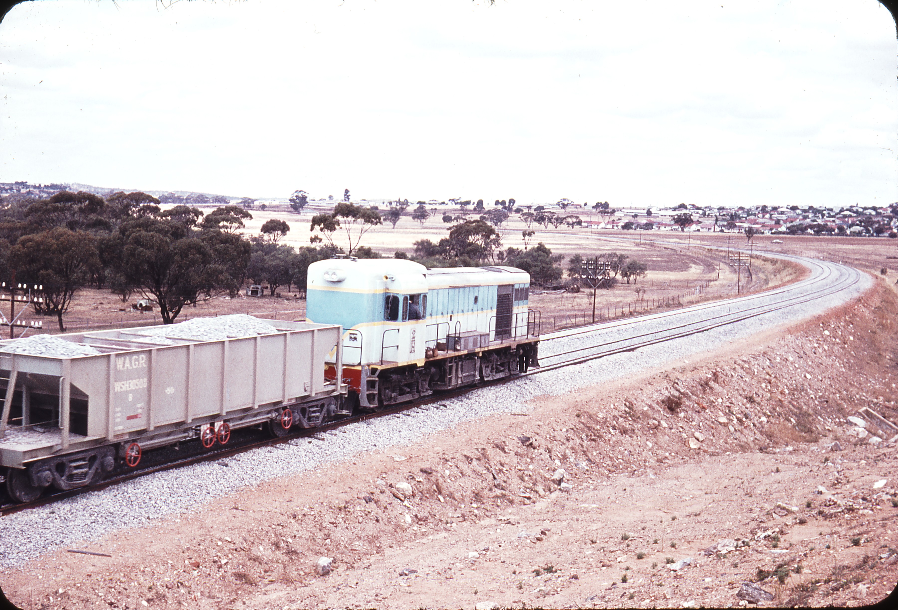 |
| Photo from Weston Langford collection showing cross braces. |
Weighting
If required, additional weight can be added by gluing lead shot or small pieces of sheet lead in the gap between the two sets of hopper doors, and/or between the various frame members of the underframe where it would not be seen in normal operation.
Painting
Either enamel or acrylic hobby paints can be used to paint the finished model.
Back to Marbelup Models Home Page